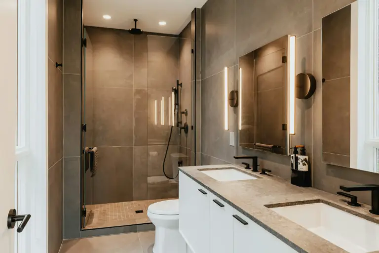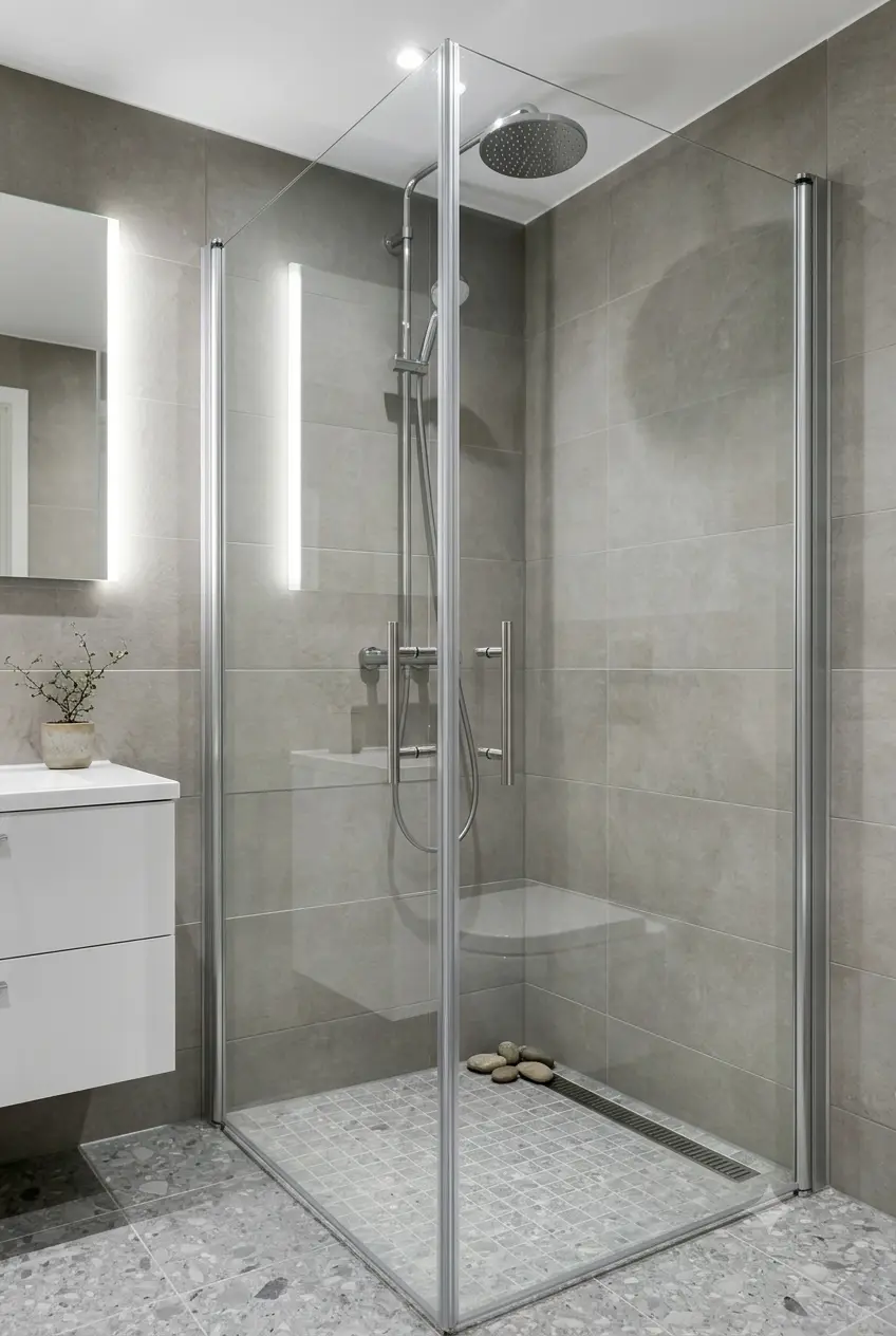
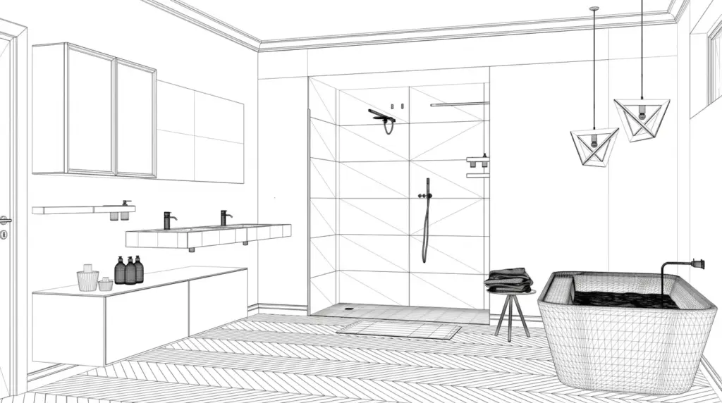
Specification errors in shower enclosures cause an average of 12-18 days of delay per commercial bathroom project, according to field data from general contractors tracking RFIs. The root cause in most cases: architects working with incomplete shower enclosure CAD details that leave dimensions, clearances, and mounting assumptions unresolved until the shop drawing phase. Getting accurate CAD files from the manufacturer before you finalize your drawings eliminates that delay entirely.
This guide covers the technical content architects need inside shower enclosure CAD drawings — from standard dimensions and component callouts to file formats and manufacturer request workflows. Use it as a checklist before your next specification submittal.
Key Takeaways
- Standard commercial glass thickness runs 8mm, 10mm, or 12mm — each requires different hinge and bracket sizing in CAD
- ADA compliance demands a minimum 36-inch clear floor space in front of the shower entry
- Frame profiles include U-channel wall mounts, header rails, and thresholds — all dimensioned differently
- Frameless enclosures need 6-8 more annotation callouts than framed units due to exposed hardware
- Most manufacturers deliver CAD files in DWG, DXF, and increasingly Revit BIM families
- Request CAD files at least 21 days before your drawing deadline to allow for custom sizing
- Sealant joints at every glass-to-wall and glass-to-threshold connection must appear in installation details
Why Accurate CAD Details Matter for Shower Enclosure Specification
A missing dimension in a shower enclosure detail costs real money. A commercial hotel bathroom renovation at a mid-tier property typically involves 200-400 rooms. If the enclosure width is off by even 15mm on a single unit type, that error repeats across every room using that layout. Rework at the site means re-cutting glass, re-drilling hardware, and rescheduling the tiling crew.
CAD details serve three functions in the specification process. First, they communicate exact dimensions to the contractor for rough-in framing and plumbing. Second, they establish hardware placement so structural connections land on blocking or studs. Third, they document material transitions — where glass meets tile, where threshold meets waterproofing membrane.
Architects who pull generic details from online libraries risk specifying a product that no manufacturer produces. The safe approach: obtain shower enclosure CAD details directly from the manufacturer for the exact model you intend to spec. This locks dimensions, hardware positions, and clearances to a real product before your drawings go out for bid.
What Information Architects Need from Shower Enclosure Manufacturers
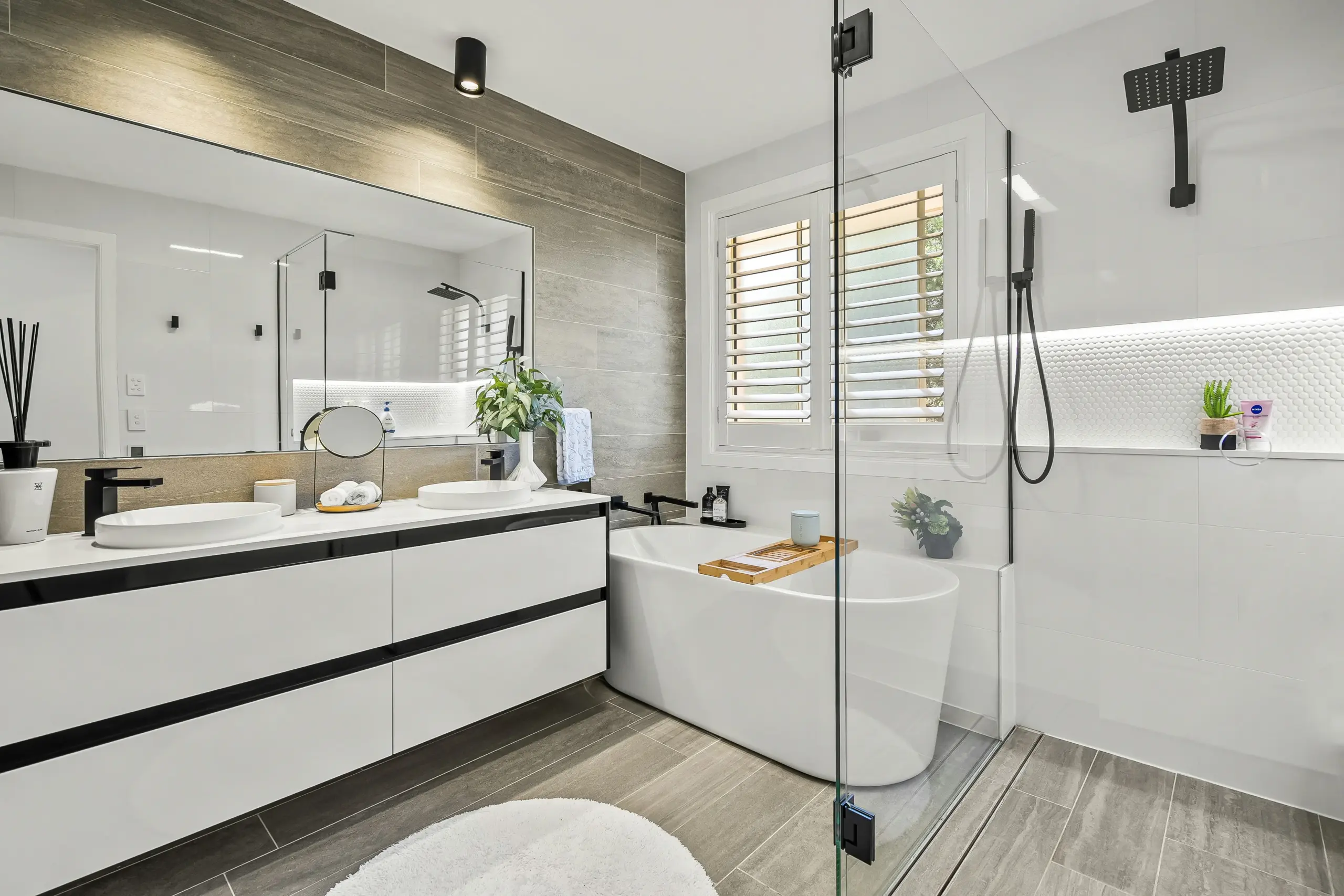
A complete manufacturer CAD package should include five file types. Each serves a different stage of the specification and construction process.
| File Type | Format | Purpose |
|---|---|---|
| Plan view drawing | DWG / DXF | Overall footprint, door swing arc, clearance zones |
| Elevation drawing | DWG / DXF | Panel heights, header placement, hardware positions |
| Section detail | DWG / DXF | Profile cross-sections, glass-to-frame connections, sealant joints |
| BIM object | RVT / IFC | 3D model with embedded parameters for Revit coordination |
| Specification sheet | Material specs, finish codes, weight, compliance data |
Request the specification sheet alongside the CAD files. The spec sheet lists glass type (tempered, low-iron, frosted), hardware finish (brushed 304 stainless steel, matte black aluminum), and weight per panel. Your structural team needs the weight to verify that ceiling-mount supports or wall brackets can carry the load.
Some manufacturers now provide Revit families with parametric controls — you adjust width and height in the family properties and the model updates automatically. This reduces the risk of dimension mismatches between your drawings and the as-built product. Ask specifically if parametric BIM objects are available before accepting static 3D blocks.
Key Components Shown in Shower Enclosure CAD Drawings
A well-detailed shower enclosure CAD drawing annotates every physical component the installer needs to assemble the unit. Missing callouts create RFIs. Here is the component checklist your detail should cover.
| Component | What the CAD Detail Must Show | Typical Tolerance |
|---|---|---|
| Frame profiles (U-channel, header, threshold) | Cross-section dimensions, corner joint type, fastener spacing | Plus or minus 0.5mm on cut length |
| Glass panels | Width, height, thickness, edge polish type, tempered marking | Plus or minus 1mm on panel dimensions |
| Pivot hinges | Center-point location from panel top and bottom edges | Plus or minus 1.5mm |
| Sliding rollers and track | Roller spacing, track mount height, adjustment range | Plus or minus 1mm |
| Handles and pulls | Mounting height from finished floor, through-bolt pattern | Plus or minus 2mm |
| Glass-to-glass clamps | Clamp position, bolt torque spec, load rating per clamp | Plus or minus 1mm |
| Sealant joints | Bead width, bead depth, sealant type at each joint | 6mm to 10mm bead width |
| Clearances | Panel-to-panel gap, door-to-frame gap, threshold gap | 3mm to 6mm typical |
Frame Profiles
Three standard profiles appear in most enclosure details. The U-channel mounts to the wall and receives the glass panel edge. The header rail spans the top of the enclosure and connects wall channels. The threshold or sill sits at floor level and provides the bottom rail for sliding doors or the dam for swing doors. Each profile has a specific cross-section dimension — typically 25mm to 38mm face width — that affects the overall enclosure footprint.
Glass Panels
CAD drawings must show glass thickness, panel dimensions, and edge treatment. Standard commercial thicknesses are 8mm for light-use applications, 10mm for standard commercial, and 12mm for heavy-duty or premium installations. Edge profiles include flat polish, beveled, or pencil polish. The drawing should note tempered glass compliance with ANSI Z97.1 or EN 12150.
Hardware Positions
Pivot hinges, sliding rollers, handles, and glass clamps all need precise location dimensions. A pivot hinge center point sits typically 150mm from the bottom edge and 150mm from the top edge of the door panel. Handle placement varies, but bar pulls mount at 1000mm-1100mm from the finished floor. Every hardware piece requires blocking or reinforcement behind the wall surface — the CAD detail must show these connection points.
Mounting Details
Wall-mount brackets, glass-to-glass clamps, and ceiling-mount supports each have different load requirements. A 12mm tempered glass panel at 1200mm wide weighs approximately 72 kg. Ceiling-mount supports must carry this full weight if the panel does not rest on a threshold. The detail should show fastener type, embedment depth, and required blocking dimensions.
Sealant Lines and Clearances
Silicone sealant at every glass-to-wall and glass-to-threshold joint prevents water migration. CAD details should show a 6mm to 10mm sealant bead width. Panel-to-panel clearances for sliding doors run 3mm to 5mm. Swing door gaps at the hinge side and latch side typically measure 3mm to 6mm. These clearances affect the overall opening size and must coordinate with your tile layout.
Standard Dimensions and Clearances to Design Around
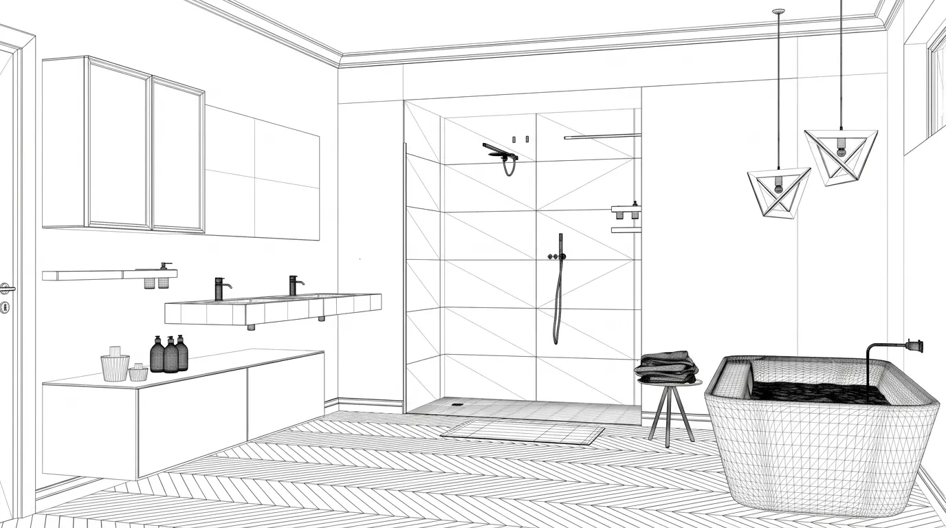
Working from standard sizes reduces lead time and cost. Custom widths add 5-7 days to production. The table below lists the most common enclosure footprints in both imperial and metric.
| Configuration | Imperial Size | Metric Size | Typical Use |
|---|---|---|---|
| Square compact | 36″ x 36″ | 900 x 900 mm | Standard hotel bathroom, single user |
| Square medium | 42″ x 42″ | 1050 x 1050 mm | Mid-range hotel, upscale residential |
| Square large | 48″ x 48″ | 1200 x 1200 mm | Premium hotel suite, accessible bath |
| Rectangle | 60″ x 36″ | 1500 x 900 mm | Master bath, walk-through configuration |
| Wide rectangle | 48″ x 36″ | 1200 x 900 mm | Standard commercial, roll-in shower |
Door widths follow their own range. Swing doors run 600mm to 900mm (24″ to 36″). Sliding doors span 600mm to 1200mm (24″ to 48″). The ADA requires 36 inches of clear floor space in front of the shower entry for wheelchair approach. Plan your toilet room layout around this number before you lock the enclosure position.
Headroom matters too. Standard panel heights range from 1800mm to 2100mm (71″ to 83″). Ceiling-mount enclosures in commercial projects often extend to 2400mm. Above 2100mm, the panel thickness typically increases from 10mm to 12mm to resist deflection. Your CAD detail must note the panel height so the structural engineer can verify lateral stability.
Frameless vs Semi-Frameless vs Framed: How CAD Details Differ by Type
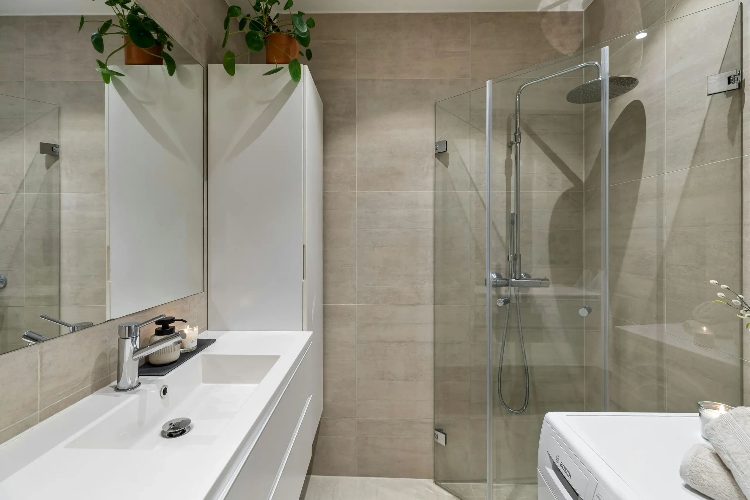
The enclosure type determines how much annotation your CAD detail requires. Each configuration exposes different components and demands different clearances.
Framed Enclosures
Framed units surround every glass edge in aluminum. The frame carries the structural load, so glass panels can be thinner — 6mm to 8mm in most cases. CAD details for framed enclosures focus on frame profile dimensions, corner joint types (45-degree miter or square butt), and screw patterns through the frame into the wall. These are the simplest details to produce and the most forgiving on site because the frame absorbs small dimensional variations.
Semi-Frameless Enclosures
Semi-frameless designs use frame channels at the walls and threshold but leave the door edges exposed. Glass thickness jumps to 8mm or 10mm. The CAD detail must show how the door panel connects to the wall channel at the hinge side and how the latch side stabilizes — usually with a magnetic seal strip or a minimal vertical channel. Hardware mounting points need tighter tolerances because there is no full frame to hide misalignment.
| Attribute | Framed | Semi-Frameless | Frameless |
|---|---|---|---|
| Glass thickness | 6mm – 8mm | 8mm – 10mm | 10mm – 12mm |
| Structural support | Full aluminum frame | Wall channels + partial frame | Clamps, pivots, ceiling brackets |
| CAD annotation callouts | Fewest (15-20) | Moderate (20-25) | Most (26-35) |
| Height tolerance | Plus or minus 3mm | Plus or minus 2mm | Plus or minus 1.5mm |
| Site adjustability | High — frame absorbs variation | Moderate | Low — glass cut to exact size |
| Typical cost range (per unit) | Lowest | Mid | Highest |
Frameless Enclosures
Frameless enclosures use 10mm or 12mm tempered glass with no surrounding frame. Structural support comes from wall-mount clamps, floor-mounted pivot hinges, and occasionally ceiling brackets. CAD details for frameless units require 6-8 more annotation callouts than framed equivalents. Every clamp position, every drill hole through the glass, every sealant joint must be dimensioned. Glass edge polish quality becomes visible and must be specified. The tolerance on panel height is typically plus or minus 1.5mm — much tighter than framed units where the channel absorbs variation.
Frameless details also need to show the relationship between glass panels at return corners. A 90-degree glass-to-glass joint uses a structural silicone bond or a glass clamp rated for the panel weight. For projects combining enclosures with fixed shower screens, the detail must show how the fixed panel connects to the returning enclosure panel.
Custom Configuration Options That Affect CAD Drawings
Commercial projects rarely use catalog sizes exclusively. Hotel bathrooms, senior living facilities, and healthcare projects all require non-standard dimensions. Here is what changes in the CAD drawing when you move off standard sizes.
Width adjustments alter panel proportions and may shift the door from a swing to a sliding configuration. A 1500mm-wide opening with a 750mm fixed panel and a 750mm sliding door requires different roller hardware and track length than a standard 1200mm unit. The CAD detail must reflect the exact roller spacing and track mounting points.
Height increases above 2100mm trigger two changes. The panel thickness typically steps up to 12mm for rigidity. Ceiling-mount supports become mandatory for panels taller than 2200mm. The CAD detail must show the ceiling bracket type, fastener pattern, and the structural connection above the ceiling plane.
Custom glass finishes — frosted, rain textured, or low-iron clear — do not change the CAD geometry but do require annotation on the specification sheet. Frosted or textured glass has a designated “face in” or “face out” orientation that affects how the panel installs in the channel.
Notched or cut-out panels for grab bars, shower seats, or niche openings require additional fabrication. The CAD detail must dimension every cutout with plus-or-minus 1mm tolerance. Tempered glass cannot be cut after the tempering process, so all cutouts must be finalized before production begins. This is the single most common source of field-fit problems in custom enclosures.
Need specification-ready CAD files for your next project? Request drawings directly from the manufacturer with your exact dimensions.
How to Request CAD Files from a Shower Enclosure Manufacturer
A structured request gets you accurate files faster. Manufacturers with dedicated engineering teams — like KJ Bath, which operates a 12-engineer R&D department — can produce custom CAD drawings from a written specification. Here is the information to include in your request.
- Opening dimensions: width, height, and depth of the shower space, measured from finished tile surface to finished tile surface
- Door configuration: swing direction (left-hand or right-hand), sliding or pivot, number of panels
- Glass specification: thickness, type (clear, low-iron, frosted, textured), edge polish
- Hardware finish: brushed stainless steel, matte black aluminum, chrome, or other
- Mounting conditions: wall type (concrete, steel stud, wood stud), ceiling height, threshold type
- Compliance requirements: ADA clearance, local building code references
- File format needed: DWG, DXF, Revit family, or PDF
Send this information as a marked-up floor plan or a dimensioned sketch. Most manufacturers respond with preliminary CAD drawings within 5-7 business days. Custom configurations with non-standard panel sizes or cutouts may take 10-14 days. Plan your request at least 21 days before your drawing deadline to allow time for review and revision.
Verify that the CAD files you receive match the manufacturer’s production capabilities. KJ Bath operates CNC double-head cutting saws and TUTO MAX CNC precision machines, which hold tolerances of plus or minus 0.5mm on aluminum cuts and plus or minus 1mm on glass panel dimensions. If a detail shows a dimension tighter than the manufacturer can hold, flag it before you issue the drawing.
For projects requiring BIM coordination, ask whether the manufacturer provides Revit families with parametric width and height controls. Parametric objects let you adjust the enclosure size in your model without waiting for the manufacturer to redraw. Not all manufacturers offer this, but the major commercial suppliers increasingly do.
Coordinating with Structural and Plumbing Teams
Shower enclosure details do not exist in isolation. They intersect with structural framing, plumbing rough-in, and waterproofing — all of which appear in other disciplines’ drawings. Coordination failures between these trades cause the most common field problems.
The structural engineer needs to know three things from the enclosure CAD detail. First, the weight of each glass panel. A 10mm tempered panel at 1000mm wide by 2000mm tall weighs approximately 50 kg. Second, the location of ceiling-mount or wall-mount bracket loads. Third, whether the wall can accept the bracket fastener type specified — concrete walls accept anchor bolts directly, but steel stud walls require backing plates or through-bolts.
The plumbing team needs to see the threshold height and drain location relative to the enclosure footprint. A zero-threshold (barrier-free) shower requires the drain to sit within a specific zone — typically centered under the shower area or offset toward the entry side for a linear drain. The enclosure CAD detail must show the threshold profile height so the plumber can set the shower pan slope to match.
Waterproofing coordination is critical. The enclosure threshold or U-channel sits on top of the waterproofing membrane. The CAD detail should show this layer sequence: structural slab, shower pan liner or membrane, mortar bed, tile, then threshold or channel. If the waterproofing contractor and the enclosure installer are different trades — they almost always are — the detail must clearly assign responsibility for sealing the membrane-to-threshold joint.
KJ Bath provides a 24-hour technical support team that handles installation and structural questions from the field. If your structural engineer has questions about bracket load capacity or fastener pullout values, the manufacturer’s engineering team can supply test data. Request this data during the design phase, not after the submittal goes out for approval.
Installation Details Architects Should Include in Drawings
Your construction documents should include at least two installation details for each enclosure type in the project. These details go beyond the product CAD drawings and show how the enclosure integrates with the building.
Wall Connection Detail
Show the full wall build-up at the enclosure mounting point. For concrete walls, detail the anchor type and embedment depth. For steel stud walls, show the backing plate dimensions — typically 150mm wide by full stud bay height, minimum 16-gauge steel. The U-channel fastens to this backing. Include the sealant bead between the channel and the finished tile surface.
Threshold Detail
Show the threshold sitting on top of the finished floor with sealant at the underside. For zero-threshold installations, show the transition from the shower pan slope to the main floor drain. Note the slope direction and rate — typically 1:48 (2%) toward the drain.
Header and Ceiling Connection
For enclosures with ceiling-mount supports, show the connection above the finished ceiling. The support rod or bracket must anchor to the structural deck or to blocking between joists. Include the fire-rating requirement if the ceiling assembly is rated — the penetration through the ceiling membrane may need a firestop sealant.
Door Hardware Mounting
Detail the hinge or pivot point with dimensions from the finished floor. Show the blocking or reinforcement behind the wall at the handle location. A bar pull handle mounted on 10mm glass with through-bolt hardware needs a minimum 50mm diameter backing plate on the opposite side of the glass.
These installation details protect you from liability. If the contractor installs the enclosure per your detail and a problem occurs, the documentation shows due diligence. If the contractor deviates from the detail, the deviation is clear and assignable.
Conclusion
Shower enclosure CAD details are not optional extras in the specification set. They are load-bearing documents that communicate dimensions, hardware positions, structural connections, and waterproofing transitions to every trade on the project. Incomplete details cause RFIs, field errors, and schedule delays — problems that compound across every repeated bathroom unit in a commercial project.
The path to clean drawings is straightforward. Obtain CAD files directly from the manufacturer for the exact product you are specifying. Verify dimensions against your floor plan before issuing the drawing. Coordinate panel weights and mounting loads with your structural engineer. Include installation details that show the full wall and floor assembly at every connection point.
Key Takeaways
- Request manufacturer CAD files at least 21 days before your drawing deadline to accommodate custom sizing and review cycles
- Standard commercial glass thickness is 10mm — step up to 12mm for panels taller than 2100mm or wider than 1200mm
- Frameless enclosures require 6-8 more annotation callouts than framed units and hold tighter tolerances (plus or minus 1.5mm on panel height)
- Every glass-to-wall and glass-to-threshold joint needs a sealant callout in the CAD detail
If your current project requires specification-ready shower enclosure details, start by contacting the manufacturer with your opening dimensions and configuration requirements. KJ Bath’s engineering team responds within 12 hours and can produce custom CAD drawings for projects of any scale. Browse the shower enclosure product range to identify the base configuration before requesting custom drawings.
Accurate CAD details prevent costly specification errors and keep your project on schedule. KJ Bath’s 12-person R&D team produces detailed drawings for every configuration we manufacture — frameless, semi-frameless, framed, sliding, and pivot. Request CAD files for your project and our team will respond within 12 hours.
KJ Bath: CAD Support and Custom Design for Architect Specifications
KJ Bath’s 12-person R&D team produces detailed CAD drawings for every enclosure configuration — frameless, semi-frameless, framed, sliding, pivot, and walk-in. The factory uses CNC double-head cutting saws and TUTO MAX precision machines to achieve tight tolerances on custom dimensions. KJ Bath supports architects with specification drawings, custom size engineering, and structural coordination. The company has supplied projects for Hilton, Marriott, and Hyatt, holding ISO9001, SGCC, and CE certifications. Sample drawings are available within 15 days, production within 30 days. Request CAD files from KJ Bath for your project.
Frequently Asked Questions
What file formats do shower enclosure manufacturers provide for CAD details?
Most manufacturers provide DWG and DXF files for 2D drawings. Increasingly, commercial manufacturers also supply Revit families (RVT) and IFC files for BIM coordination. PDF specification sheets accompany the CAD files with material data, finish codes, and compliance information. Always confirm the file format before your deadline — converting between formats can lose annotation layers.
How long does it take to get custom CAD drawings from a shower enclosure manufacturer?
Standard configurations with catalog sizes typically arrive within 5-7 business days. Custom sizes, non-standard glass finishes, or panels with cutouts require 10-14 business days. Manufacturers with in-house CNC production — like KJ Bath, which operates TUTO MAX CNC precision machines — can verify feasibility and produce drawings simultaneously, reducing total turnaround. Plan your request at least 21 days before your drawing issue date.
What glass thickness should I specify for a commercial hotel shower enclosure?
For commercial hotel applications, 10mm tempered glass is the standard specification. It balances structural rigidity, weight, and cost. Use 8mm only for light-use residential applications or where the enclosure is fully framed. Use 12mm for premium installations, panels taller than 2100mm, or frameless enclosures where the glass must resist lateral deflection without frame support. The hardware — hinges, clamps, and brackets — must be rated for the glass thickness you specify.
Can shower enclosure CAD details be used directly in Revit or BIM models?
2D DWG files import into Revit as underlays for detailing but do not carry parametric data. For full BIM coordination, request a Revit family file from the manufacturer. Parametric families let you adjust width, height, and door configuration within the family properties. Not all manufacturers produce parametric families yet, but the capability is growing among commercial suppliers with dedicated engineering teams.
What is the minimum clearance required in front of a shower enclosure for ADA compliance?
The ADA requires a 36-inch by 36-inch clear floor space positioned in front of the shower entry. This clearance must be free of obstructions including the door swing arc. For swing doors, the door must not swing into this required clear space. Sliding doors eliminate the swing clearance issue but require wider overall openings. Always verify local code amendments — some jurisdictions exceed the federal ADA minimum.